1. Appearance defects Appearance defects (surface defects) refer to defects that can be found from the surface of the workpiece without the aid of instruments. Common appearance defects include undercuts, weld bumps, depressions, and welding deformations, and sometimes surface pores and surface cracks, and the roots of single-sided welding are not fully welded.
A、Undercut
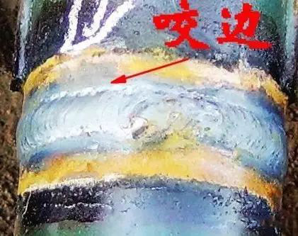
It refers to the depression or groove formed in the base metal part along the weld toe. It is the gap left by the arc melting the base metal at the edge of the weld without being fully supplemented by the deposited metal.
The main reason for undercutting is that the arc heat is too high, that is, the current is too large, the speed of the strip is too small, the angle between the electrode and the workpiece is not correct, the swing is unreasonable, the arc is too long, the welding sequence is not reasonable, etc. Undercut. The magnetic bias of the arc during DC welding is also a cause of undercut. Certain welding positions (vertical, horizontal, vertical) will aggravate the undercut, which reduces the effective cross-sectional area of the base material and reduces the load-bearing capacity of the structure. At the same time, it will cause stress concentration and develop into a crack source.
Prevention of undercuts: Correcting the operating posture, choosing reasonable specifications, and adopting a good way of transporting will all help eliminate undercuts. When fillet welds are welded, alternating current welding instead of direct current welding can also effectively prevent undercut.
B、Weld
The liquid metal in the weld flows to the unmelted base material that is not heated enough or overflows from the root of the weld, and the metal nodules formed after cooling that are not fused with the base metal are weld nodules. Welding specifications are too strong, the welding rod melts too fast, the quality of the welding rod is poor (such as eccentricity), the characteristics of the welding power source is unstable, and the operation posture is not suitable.
Welding bumps are often accompanied by non-fusion and slag inclusion defects, which can easily lead to cracks. At the same time, the weld bead changes the actual size of the weld, which will cause stress concentration. Welding bumps on the inside of the tube reduce its inner diameter, which may cause blockages of fluids.
Measures to prevent weld bumps: keep the weld in the flat welding position, correctly select the specifications, select the non-eccentric welding rod, and operate reasonably.
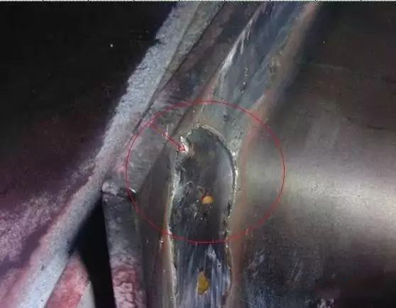
C、Pit
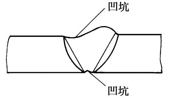
The pit refers to the part of the surface or back of the weld that is lower than the base material.
The pits are mostly caused by the welding rod (wire) not staying for a short time when the arc is closed (the pits at this time are called arc pits). When vertical and horizontal welding, the root of the back of the weld is often concave. The pit reduces the effective cross-sectional area of the weld, and the crater often has crater cracks and crater shrinkage.
Measures to prevent pits: Choose a welding machine with a current attenuation system, try to choose a flat welding position, choose a suitable welding specification, and let the welding rod stay in the molten pool for a short time or swing in a ring when closing the arc to fill the arc pit.
D、Not full
Under-welded refers to continuous or intermittent grooves on the surface of the weld. Insufficient filler metal is the root cause of insufficient welding. The specification is too weak, the welding rod is too thin, and the improper handling of the rod will lead to insufficient welding.
Under-soldering also weakens the weld seam, which is prone to stress concentration. At the same time, the cooling rate is increased due to the weak specification, which is likely to cause pores and cracks.
Measures to prevent under-welding: increase the welding current, and add welded cover welds.
E、Burn through
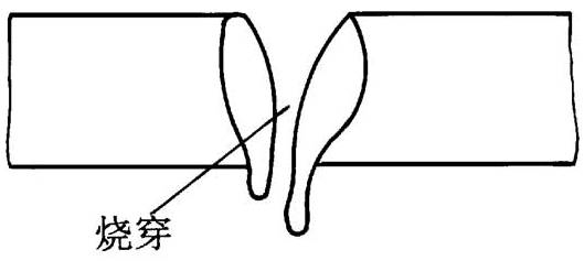
Burn-through means that during the welding process, the penetration depth exceeds the thickness of the workpiece, and the molten metal flows out from the back of the weld, forming a perforation defect.
If the welding current is too high, the speed is too slow, and the arc stays at the weld for too long, burn-through defects will occur. If the gap between the workpieces is too large and the blunt edge is too small, it is easy to burn through.
burn-through is an impermissible defect in boiler pressure vessel products. It completely destroys the weld seam and causes the joint to lose its connection and load-bearing capacity.
Prevention measures: Choose a smaller current and match the appropriate welding speed to reduce the assembly gap, add a backing plate or a pad on the back of the weld, and use pulse welding to effectively prevent burn-through.
F、Other surface defects
(1) Poor forming means that the appearance and geometric dimensions of the weld do not meet the requirements. There are ultra-high welds, uneven surface, and wide welds, and the transition from weld to base metal is not smooth.
(2) Wrong edge means that two workpieces are staggered by a certain position in the thickness direction. It can be regarded as a weld surface defect and an assembly forming defect.
(3) Collapse During single-sided welding, the liquid metal collapses toward the back of the weld due to excessive heat input and too much molten metal. After forming, the back of the weld protrudes and the front collapses.
(4) Surface pores and arc crater shrinkage.
(5) Various welding deformations such as angular deformation, twisting, wave deformation, etc. are all welding defects. Angle deformation is also an assembly forming defect.
Two. Stoma and slag inclusion
A, stomata
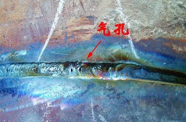
Porosity refers to the cavity formed when the gas in the molten pool does not escape before the metal solidifies and remains in the weld. The gas may be absorbed by the molten pool from the outside, or may be generated by the reaction in the welding metallurgy process.
(1) Classification of stomata
stomata are divided into spherical stomata and worm-like stomata according to their shape; they can be divided into single stomata and cluster stomata in number. Grouped stomata are divided into evenly distributed stomata, dense stomata and chain stomata. According to the gas composition in the pores, there are hydrogen pores, nitrogen pores, carbon dioxide pores, carbon monoxide pores, oxygen pores, etc. The fusion welding pores are mostly hydrogen pores and carbon monoxide pores.
(2) The formation mechanism of stomata
The solubility of gas in solid metal at room temperature is only one tenth to one hundredth of that in high temperature liquid metal. During the solidification of molten pool metal, a large amount of gas will escape from the metal. When the solidification rate is greater than the gas escape rate, pores are formed.
(3) The main cause of stomata
The surface of the base metal or filler metal has rust, oil stains, etc., the electrode and flux are not dried, which will increase the amount of pores, because the moisture in the rust, oil stains, electrode coating, and flux decomposes into gas at high temperatures, increasing the gas in the high temperature metal content. If the welding line energy is too small, the cooling rate of the molten pool is high, which is not conducive to the escape of gas. Insufficient deoxidation of weld metal will also increase oxygen pores.
(4) The hazard of stomata
porosity reduces the effective cross-sectional area of the weld and makes the weld loose, thereby reducing the strength of the joint, reducing plasticity, and causing leakage. Pores are also factors that cause stress concentration. Hydrogen holes may also contribute to cold cracks.
(5) Measures to prevent blowholes
A. Remove the oil, rust, moisture and debris from the welding wire, the working groove and the surface nearby.
B. Use alkaline electrode and flux, and dry thoroughly.
C. Adopt DC reverse connection and use short arc welding.
D. Preheat before welding to slow down the cooling rate.
E. Use stronger specifications for welding.
B, slag inclusion
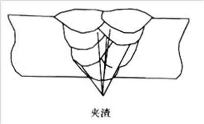
Slag inclusion refers to the phenomenon that the molten slag remains in the weld after welding.
(1) Classification of slag inclusion
A. Metal slag inclusion: refers to metal particles such as tungsten and copper remaining in the weld. It is customarily called tungsten inclusion and copper inclusion.
B. Non-metallic slag: refers to the unmelted electrode coating or flux, sulfide, oxide, and nitride remaining in the weld. The metallurgical reaction is incomplete and the slag removal is not good.
(2) Distribution and shape of slag inclusion
There are single point slag inclusion, strip slag inclusion, chain slag inclusion and dense slag inclusion
(3) Causes of slag inclusion
a. The groove size is unreasonable; b. There is dirt in the groove; c. When multi-layer welding, the slag removal between layers is not complete; d. The welding line energy is small; e. The heat dissipation of the weld is too fast, and the liquid metal solidifies too fast ; f. Electrode coating, the chemical composition of the flux is unreasonable, and the melting point is too high; g. When tungsten inert gas shielded welding, the power source polarity is improper, the electric and current density is large, and the tungsten electrode melts and falls off in the molten pool. h. During manual welding, the electrode swings badly, which is not conducive to the slag floating. According to the above reasons, corresponding measures can be taken to prevent slag inclusion.
(4) The hazards of slag inclusion
The hazard of point-shaped slag inclusion is similar to that of pores. The slag inclusion with sharp corners will cause stress concentration at the tip, and the tip will develop into a crack source, which is more harmful.
Three, crack
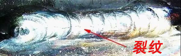
The bonding of atoms in the weld is destroyed, and the gap created by the formation of a new interface is called a crack.
A. Classification of cracks
According to the size of the crack, it is divided into three categories:
(1) Macro crack
Cracks visible to the naked eye.
(2) Micro crack
can only be found under a microscope.
(3) Super microcrack
can only be found under a high magnification microscope, generally refers to intergranular cracks and intragranular cracks.
From the point of view of temperature, cracks are divided into two types:
(1) Hot crack
Cracks generated near the Ac3 line. Generally, it appears immediately after welding, which is also called crystal crack. This kind of two cracks mainly occurs in the grain boundary, and the crack surface has oxidation color and loses its metallic luster.
(2) Cold cracks: refers to cracks that occur after the welding is cooled to the martensite transformation temperature below the M3 point. Generally, it appears after a period of time (a few hours, days or even longer) after welding, so it is also called delayed cracking.
According to the cause of the crack, the crack can be divided into:
(1) Reheat crack
The crack occurs when the joint is cooled and then heated to 500~700℃. Reheat cracks are generated in the coarse-grain zone in the heat-affected zone of the welding of precipitation-strengthened materials (such as metals containing Cr, Mo, V, Ti, and Nb), and generally develop from the fusion line to the coarse-grain zone in the heat-affected zone. Features of intergranular cracking.
(2) Laminar tear
is mainly due to the formation of anisotropy due to the inclusion of impurities such as sulfide (MnS) and silicate in the rolling process. Under the use of welding stress or external restraint stress, the metal debris along the rolling direction cracks.
(3) Stress corrosion cracking
Cracks produced under the combined action of stress and corrosive media. Except for residual stress or restraint stress, stress corrosion cracking is mainly related to the structure and shape of the weld.
B, the hazard of cracks
Especially cold cracks, the harm it brings is catastrophic. Except for a very small number of pressure vessel accidents in the world caused by unreasonable design and improper material selection, most of the pressure vessel accidents are caused by brittle failure caused by cracks.
C, hot crack (crystal crack)
(1) The formation mechanism of crystal cracks
Thermal cracks occur at the end of the solidification of the weld metal. The sensitive temperature zone is roughly in the high temperature zone near the solidus. The most common thermal crack is crystal cracks. The reason for its formation is that during the solidification of the weld metal, crystal segregation causes impurities to be generated. The low melting point eutectic is enriched in the grain boundary to form a so-called "liquid film". Between the specific sensitive temperature zone (also known as the brittle temperature zone), its strength is extremely small, and it is subjected to tensile stress due to the solidification and shrinkage of the weld. Eventually cracks form cracks.
The most common case of crystal cracks is cracks along the length of the weld center, which is a longitudinal crack, and sometimes occurs between two columnar crystals inside the weld, which is a transverse crack. Crater crack is another form, common hot crack.
Hot cracks are all cracks along the grain boundary, which usually occur in gas welds of carbon steel, low alloy steel, austenitic stainless steel and other materials with more impurities
(2) Factors affecting crystal cracks
A Influence of alloying elements and impurities The increase of carbon element and impurity elements such as sulfur and phosphorus will expand the sensitive temperature zone and increase the chance of crystal cracks.
B. The effect of cooling rate The cooling rate increases, one is to increase the crystallization segregation, and the other is to increase the crystallization temperature range, both of which will increase the chance of crystal cracks;
C. The influence of crystallization stress and restraint stress In the brittle temperature zone, the strength of the metal is extremely low, and the welding stress causes the part of the metal to be stretched. When the tensile stress reaches a certain level, crystal cracks will appear.
(3) Measures to prevent crystal cracks
A. Reduce the content of harmful elements such as sulfur and phosphorus, and use materials with lower carbon content for welding. b. Add certain alloying elements to reduce columnar crystals and segregation. Such as aluminum, sharp, iron, mirror, etc. can refine the grain. , c. Use a weld with a shallower penetration to improve the heat dissipation conditions so that the low melting point substance floats on the surface of the weld and does not exist in the weld. d. Reasonably select welding specifications, and use preheating and post-heating to reduce the cooling rate. e. Use a reasonable assembly sequence to reduce welding stress.
D, reheat crack
(1) Characteristics of reheat cracks
A. Reheat cracks are generated in the overheated coarse-grained zone of the welding heat affected zone. Produced in the process of reheating such as post-weld heat treatment.
B. Reheating crack generation temperature: carbon steel and alloy steel 550~650℃, austenitic stainless steel is about 300℃
C. Reheat cracks are grain boundary cracks (crack along the grain).
D. It is most easily produced in precipitation strengthened steel.
E. Related to welding residual stress.
(2) Mechanism of reheat crack
a. There are many explanations for the mechanism of reheat cracking. Among them, the explanation of the model cracking theory is as follows: The metal in the near-fracture zone will strengthen the phase carbide (such as iron carbide, carbonization, carbonization mirror, and carbonization) under the action of high temperature thermal cycling. Etc.) is deposited on the dislocation zone in the crystal, so that the intragranular strengthening strength is much higher than the grain boundary strengthening, especially when the strengthening phase is dispersed and distributed in the crystal grains, it hinders the local adjustment of the crystal grains and hinders the crystal grains. In this way, the plastic deformation caused by stress relaxation is mainly borne by the grain boundary metal. Therefore, when the grain boundary stress is concentrated, cracks will occur, the so-called mold cracking.
(3) Prevention of reheat cracks
A. Pay attention to the strengthening effect of metallurgical elements and their influence on reheat cracking. b. Reasonably preheat or use post heat to control the cooling rate. c. Reduce residual stress to avoid stress concentration. d. Try to avoid the sensitive temperature zone of reheat cracks or shorten the residence time in this temperature zone during tempering.
E, cold crack
(1) The characteristics of cold cracks
A. Produced at a lower temperature and after a period of time after welding, it is also called delayed cracking. b. Mainly produced in the heat-affected zone, but also in the weld zone. c. Cold cracks may be intergranular cracking, transgranular cracking or a mixture of both. d. The component damage caused by cold cracks is a typical brittle fracture.
(2) Cold cracking mechanism
A. The hardened structure (martensite) reduces the plastic reserve of the metal. b. The residual stress of the joint causes the weld to be pulled. c. There is a certain amount of hydrogen in the joint.
Hydrogen content and tensile stress are two important factors for cold cracking (referred to here as hydrogen-induced cracking). Generally speaking, the arrangement of atoms in a metal is not completely ordered, but has many microscopic defects. Under the action of tensile stress, hydrogen diffuses and accumulates to high-stress areas (defects). When hydrogen accumulates to a certain concentration, it will break the bond of atoms in the metal, and some microscopic cracks will appear in the metal. The stress continues to act, hydrogen continues to accumulate, and the microscopic cracks continue to expand, until they develop into macroscopic cracks and finally break. Determine whether cold cracks occur or not, there is a critical hydrogen content and a critical stress value. When the hydrogen concentration in the joint is less than the critical hydrogen content, or the stress is less than the critical stress, cold cracks will not occur ( That is, the delay time is infinite). Among all the cracks, cold cracks are the most harmful.
(3) Measures to prevent cold cracks
A. Use low-hydrogen alkaline electrode, strictly dry, store at 100~150℃, take it for use.
B. Increase the preheating temperature, adopt post-heating measures, and ensure that the interlayer temperature is not less than the preheating temperature, and choose reasonable welding specifications to avoid foreign hard structures in the weld
C. Use reasonable welding sequence to reduce welding distortion and welding stress
d. Carry out hydrogen elimination heat treatment in time after welding.
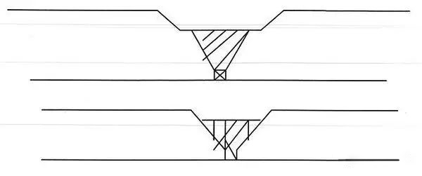
Four, not penetration
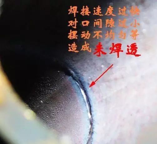
Incomplete penetration refers to the phenomenon that the base metal is not melted and the weld metal does not enter the root of the joint.
A, the cause of incomplete penetration
(1) The welding current is small and the penetration depth is shallow.
(2) The size of the groove and the gap is unreasonable, and the blunt edge is too large.
(3) The effect of magnetic bias.
(4) Electrode eccentricity is too large
(5) Poor cleaning between layers and welding roots.
B, the hazards of incomplete penetration
One of the hazards of incomplete penetration is to reduce the effective cross-sectional area of the weld and reduce the strength of the joint. Secondly, the damage caused by stress concentration caused by incomplete penetration is much greater than the damage caused by strength reduction. Incomplete penetration seriously reduces the fatigue strength of the weld. Incomplete penetration may become the source of cracks and is an important cause of weld damage. The damage caused by the stress concentration caused by incomplete penetration is much greater than the damage of the strength drop. Incomplete penetration seriously reduces the fatigue strength of the weld. Incomplete penetration may become the source of cracks and is an important cause of weld damage.
C, prevention of incomplete penetration
Using larger current to weld is the basic method to prevent incomplete penetration. In addition, when welding fillet welds, alternating current is used instead of direct current to prevent magnetic bias. The groove is reasonably designed and cleaning is strengthened. Measures such as short arc welding can also effectively prevent incomplete penetration.
Five, not fused
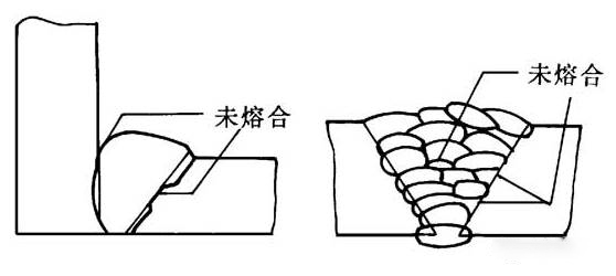
Unfusion refers to the defect that the weld metal and the base metal, or the weld metal are not melted together. According to its location, the non-fusion can be divided into three types: the groove is not fused, the interlayer is not fused, and the root is not fused.
A. Reasons for non-fusion defects: (1) The welding current is too small; (2) The welding speed is too fast; (3) The angle of the welding rod is incorrect; (4) The arc blow phenomenon has occurred; (5) The welding is in down-slope welding Location, the base material has been covered by molten iron before melting; (6) Dirt or oxide on the surface of the base material affects the melting and bonding between the deposited metal and the base metal.
B. Harm of non-fusion: non-fusion is a kind of area defect. The reduction of the load-bearing cross-sectional area due to the non-fusion of the groove and the non-fusion of the root is very obvious, the stress concentration is also relatively serious, and its damage is second only to cracks.
C. Prevention of non-fusion: use a larger welding current, perform welding operations correctly, and pay attention to the cleanness of the groove.
6. Other defects (1) The chemical composition or structural composition of the weld does not meet the requirements: the improper matching of the welding material and the base metal, or the element burning during the welding process, etc., may easily change the chemical composition of the weld metal or cause welding The seam tissue does not meet the requirements. This may bring about a decrease in the mechanical properties of the weld, and also affect the corrosion resistance of the joint.
(2) Overheating and overburning: If the welding specifications are used improperly, the heat-affected zone stays at high temperature for a long time, which will cause the grains to become coarse, that is, the overheated structure will appear. If the temperature rises further and the residence time is longer, the grain boundaries may be oxidized or partially melted, resulting in an overburnt structure. Overheating can be eliminated by heat treatment, and overburning is an irreversible defect.
(3) White spots: Fish-like white spots appearing on the tensile section of the weld metal, that is, the white spots from point F are caused by hydrogen accumulation, which is extremely harmful.